With the recent advances in unmanned aerial vehicles (UAV) and drone technology, foam processing fills the void in manufacturing, research, and development. Especially when developing airfoils and fuel reservoir explosion containment devices. Unmanned aerial vehicles (UAV’s) are rapidly gaining popularity in government, military, science, and hobby use applications. Aerial vehicles might be equipped with a package to be delivered or a camera to analyze geography.
Specific types of foam are used inside fuel tanks to help mitigate fuel slosh during vehicle elevation and direction changes, and to help contain debris and pressure in the case of an accidental ignition inside the tank. 3D CNC machines are beneficial for these needs, and accuracy and repeatability have become paramount and integral in the production of aerospace components.
Foam proves to be a very useful medium for these purposes due to its inexpensive cost and ease of machining, as well as ability to produce parts quickly and efficiently. For research, development, and rapid prototyping, foam materials are second to none.
Benefits Of Using Foam in Aerospace Development
Expanded Polystyrene foam (EPS) is a lightweight, rigid, cellular plastic material that is commonly utilized for a range of products. Due to its popularity, several different variations of foams have been developed for a multitude of purposes. In aerospace applications, the most common types that our clients deal with are Expanded Polystyrene (EPS) and Polyurethane (PU) foams. Polyurethane foams are typically softer and used for cushioning and interior applications. Both Expanded Polystyrene (EPS) and Polyurethane (PU) foams can be cut with a cnc foam cutter, making the FROGWire™ a valuable asset in any aerospace development facility.
Aside from our hot wire cutter, the FROG3D® family of products also includes a large-format automated milling machine – the FROGMill™ . The FROGMill™ stands out for its robust build quality, long cutting tools, and oversized frame. The larger frame and higher gantry allow for larger parts to be machined as a whole, eliminating the need for post-assembly work, and maintaining tolerances in the overall geometries with precision.
Easy to program and operate: FROG3D® systems provide users with a turn-key manufacturing solution that works ‘out of the box’ without the need to locate multiple vendors for individual elements of the system. Professional training and support directly from the Streamline Automation team covers training on everything from CNC maintenance and operation to software, and even processing practices to ensure long-term success.
Straight to the testing lab: Using automated equipment allows for the machining of a more complete part, so the steps required after it takes shape are limited. In traditional practices, a part of the process of development would have to be made multiple times, usually by hand. These parts would be put through the quality inspection and testing process, where results would be measured and a report would be completed. The report would go back to the design process, where adjustments would be made to the testing model, and the part created again to new specifications. For this reason, the speed at which the sample parts are made affects the end goals substantially. Precision CNC foam cutting and milling equipment expedites the process dramatically, saving the user time and resources.
Precision and accuracy: CNC equipment like the FROGMill™ and FROGWire™ follows computer-generated designs to produce intricate and detailed parts. This level of precision can be a challenge to achieve manually where there is always room for human error. Using high quality foam cutting equipment will ensure that your airfoils are created exactly to the specified requirements.
Repeatability: A major highlight of automated CNC equipment is its ability to produce repeated parts exactly like one another. As the tool approach, order of operations, and geometry surfaces are pre-programmed in a digital environment, repeating the process is as simple as loading the cut file and providing the machine with material and the appropriate tool. Whether you need to run a file multiple times, or you just need one now and another a year from now, you can count on the parts being identical in every way.
Scalability: During the testing and prototyping phase of a project, you might want to build things at a different scale. With automated CNC equipment, the scaling is being handled in a digital environment, so accuracy regardless of size is to the specified requirements.
Future Proof: CNC files are digital, and can be stored on a computer, a portable disc, or even on a cloud. This means that you do not need to maintain storage facilities and inventory of physical objects. Masters and molds can be stored as digital files and recreated when the need arises.
Streamline Automation’s FROG3D® System in Aerospace
With cutting-edge technology, commercial-grade construction, and industry-leading training and support, Streamline Automation’s FROG3D® System closes the gap between digital design and production.
From preliminary design to completed project, our equipment provides intelligent and intuitive solutions for every step of the fabrication process. The fully integrated range of our FROG3D® System includes 3D scanning, digital modelling, hot wire foam cutting, 3D CNC milling, and protective coating application products that have been specifically engineered for your distinct fabrication requirements.
FROGScan Flash™ – Peel 3
With the FROGScan™ Flash-Peel 3, it is possible to translate any physical object into an accurate 3D scan that can be perfectly replicated or enlarged digitally. By utilizing advanced white light technology, the FROGScan™ Flash – Peel 3 is able to capture a digital 3D scan with very little experience or skills required. It is a standalone and portable solution that can be conveniently transported and set up when and where it is required.
The FROGScan™ Flash – Peel 3 is a powerful tool for reverse engineering. It digitally replicates the surfaces of physical objects for digital verification, modification, or data storage.
FROGWire™
Hotwire cutting processes foam quickly and cleanly using radiant heat. For this reason, the surface finish when using Expanded Polystyrene (EPS) foam as a medium is very smooth and consistent. Foam hot wire cutters such as the FROGWire™ offer an easy-to-use controller system to monitor and guide the hot wire cutting process. Files that contain 2D or 3D model designs can be imported directly to the G-code-based controller which provides the machine with the toolpath automatically.
In addition, the FROGWire™ has multi-axis capabilities and a rotational axis. This multidimensional design increases the complex structures available for cutting and forming and enables the FROG3D® System to increase accuracy and minimize operation time and cost.
FROGMill™
The FROGMill™ stands out against other gantry-style CNC routers due to its large processing size and stable construction. Using high-quality drive and motion control systems, the FROGMill™ can achieve complicated surface geometries and repeat the processes accurately. With the addition of the 4th lathe axis, the FROGMill™ can approach specific cut areas from different directions to achieve the best possible results when compared to other CNC milling machines for sale.
Because of its robust frame and industrial spindle, the FROGMill™ can also cut other materials, such as varying densities of foam, high density urethanes (HDU), wood and plastics. This versatility makes it a great system for a wider range of requirements than just foam processing. The ability to process multiple materials on one platform is a major benefit to businesses. This keeps staff trained on a single system for a range of applications and use cases, and processes are much more efficient.
How to Create a Tapered Wing for Aerospace Applications Using the FROGWire™
When developing a new CNC project, there are three primary stages:
1) Design: This is the initial drawing or Computer Aided Design (CAD) model.
2) Tooling: This phase involves creating the tool paths with Computer Aided Manufacturing (CAM) software.
3) Machining: This step requires running the tool paths on the machine.
Using FROG3D® Software for Programming Tapered Wings in EPS Foam
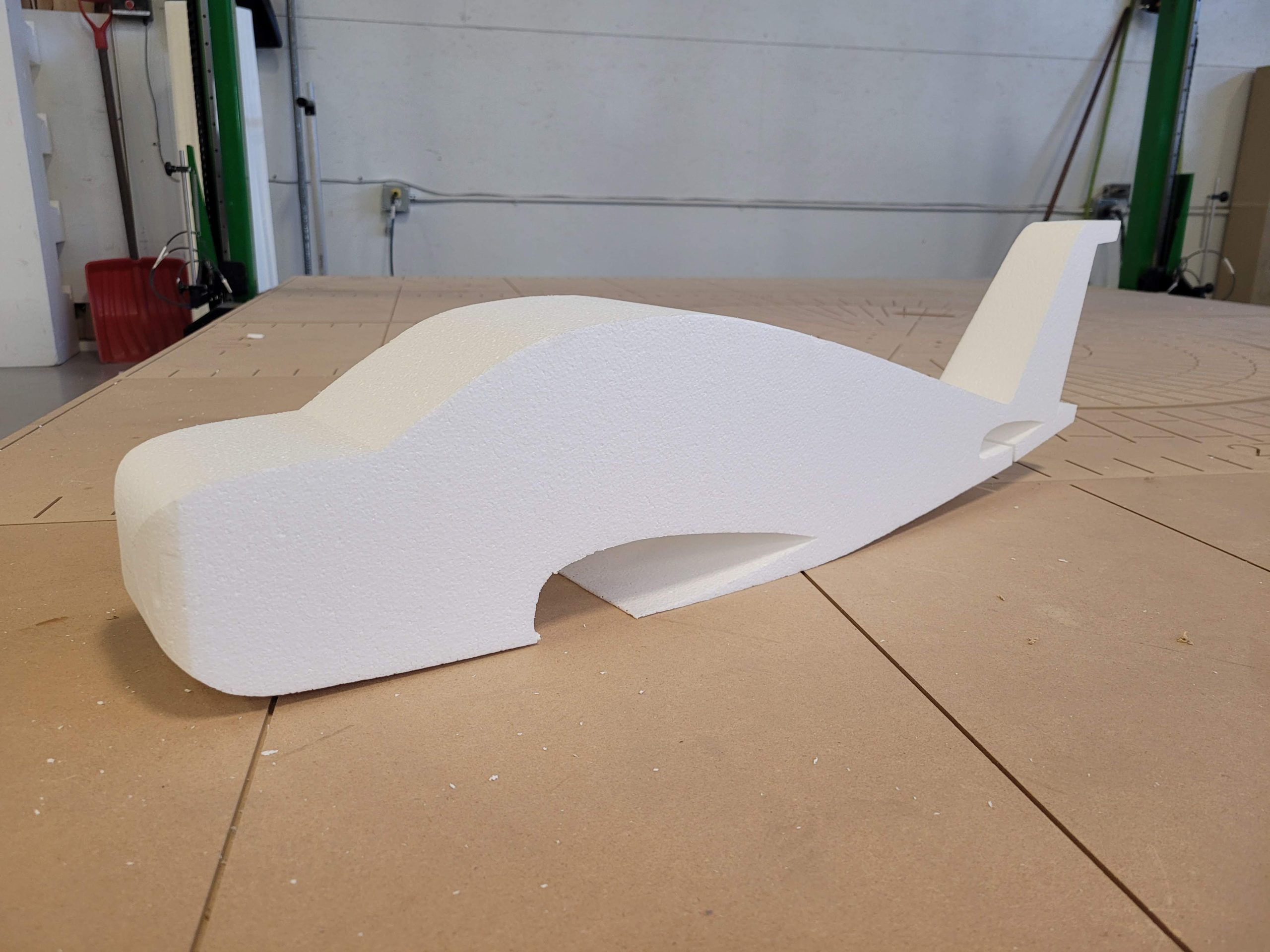
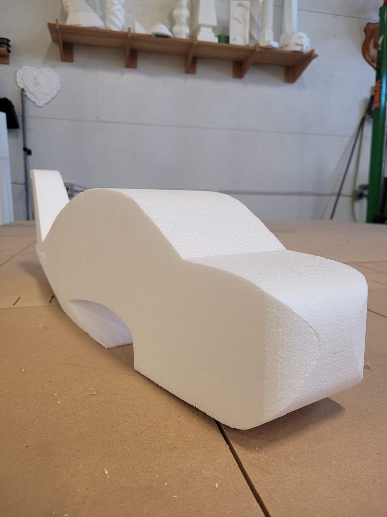
To help translate the benefits of CNC machines in aerospace applications, we created a small model airplane using Expanded Polystyrene (EPS) foam on the FROGWire™ hot wire cutting system.
We utilized Streamline Automation’s proprietary FROGShape™ software to program a series of tapered cuts, creating a left and right wing shape that remained connected as a single part.
Step 1: Design
During the first phase of the project, we needed to decide the best approach and landed on creating the plane from a few different sections. Using drawing software, we created multiple profiles for each element of the project including the wing, tail, and fuselage sections. For this particular project we utilized Vectric Aspire due to it’s powerful vector drawing tools and CAM functions for milling operations.
The fuselage required two profiles – a side profile and a top-down profile. We did not require a detailed blueprint to gather these profiles as we were not trying to recreate a complicated model. For this example, we gathered a few reference images online before deciding on our favourites. After importing the image into Vectric Aspire, we were able to use the trace function and node-editing to clean up the design. We created one half of the profile and mirrored it, to ensure that each side of the profile was identical. We also plotted out the wing and tail – using the side profile indicated the location of the wings on the body, and the top-down view gave us the width, length, and taper of the wings.
The shape of the wing is a paramount consideration when doing aerodynamics testing. We were not creating this for the purpose of any further testing, but it was still simple to find a few examples of airfoil profiles online. We used an image to trace out a general profile and then compared their widths to the design of the planform. We scaled the profile of the wing to match the wider and narrower ends of the wing and noted the distance between the two profiles. We used the same strategy for the tail profiles. The only difference in this case is that the taper is more extreme, as the two profiles rest much closer to each other.
These drawings were all exported, and then imported into FROGShape™ for the next stage of programming.
Step 2: Tooling
This phase involves creating the tool paths with Computer Aided Manufacturing (CAM) software. For files on the FROGWire™, we use our FROGShape™ CAM software. FROGShape™ was custom-built to develop intricate processing files on the FROGWire™. We put a lot of time into ensuring the software was simple to understand, and the files easy to execute. Having full control over both machine manufacturing and software development puts Streamline Automation in a unique position to develop simple processes for potentially complex projects.
FROGShape™ accepts the drawing files that were exported from our design. It requires a DXF or SVG file, which are extremely common file types. The first piece we started with was the fuselage, utilizing the two profiles, and leaving out the wings. The location of the wings became cut-out areas so we could insert the wings when all the parts were cut. There were two files created for this step, intending to rotate the block between each profile. To keep everything in line, we just used a common start position so the cuts would naturally align with each other.
The tapered wings were a little more complicated, but the FROGShape™ software made it as simple as possible. For programming tapered cuts, this piece of software requires the left and right drawing files and the distance between the two. It then uses its powerful algorithms to calculate the necessary motion of the machine arms, creating a perfect tapered product.
We took it a step further in this case and ran three files on the same part – the left side taper, the right-side taper, and the straight section in between that would fit into the fuselage. This is more involved than a standard taper cut, but FROGShape™’s visual aids ensure you are setting things up as intended before proceeding to CNC machining. You can also be sure that the files will be generated correctly and watch the cut execute virtually before bringing your files to the machine.
Step 3: Machining
Thanks to the simple setup and instructions from FROGShape™, machining becomes the easiest step of the process when creating this piece. We used T3 Expanded Polystyrene (EPS) foam for this project because the wings were a bit thin, and a stiffer material was best for longevity. Selecting the proper machining method and material is a critical step in ensuring success with any project.
The fuselage was cut from two directions. The foam block was rotated manually because it was not a very large part. For larger parts, the rotary axis is used to automate the rotation needed between cuts.
Using the same strategy – three consecutive files were run in the same material block to achieve the final wing parts. Because a common zero position was used during programming, this meant there was no re-locating or material movements between the files. We just ran the three consecutive files before pulling the part from the block and this made for a fast, effective machining strategy for this piece.
Conclusion
Whether it’s for real-world aerospace applications or a simple aerospace model, creating parts is as simple as ever with Streamline Automation’s FROG3D® System. Contact us today for a tailored quote on everything from CNC routers and hot wire cutting systems, to 3D scanning solutions, integrated software, and training.
